The objective of this research is to size a refrigeration installation adaptable to the site of the Thinwgul market 1.5 km from downtown Mamou with an area of 4269 m2 in the Republic of Guinea for the conservation of fish. During this study, we determined the main parameters essential for the proper functioning of the cold room for conservation, which are among others: compressor (3 kW), condenser (9.135 kW and 9.67 m2); evaporator 59 m2); regulator (0.38.10-4 m3/h and 8.7 bar); pipes: suction (21,090.10⁻4 m2), discharge (2,603.10⁻4 m2); cooling performance coefficient: real (3.15 and 4.06), ideal (4.71 and 4.89). Then, according to the analysis of these main results obtained during this study, namely mainly the coefficients of real and ideal refrigeration performance, this suggests a proposal for a refrigeration system with a power of 7.10 kW. The refrigerant used in this study is Hydrochlorodifluorocarbon (CHF2Cl) or refrigerant 22 (R22).
Keywords
Refrigeration System Design
Cold Room Conservation
Fish Preservation
INTRODUCTION
On a global scale, the production of cold for comfort, conservation and refrigeration needs appear to be a major energy issue. It has many applications in a wide variety of fields (food industries, medicine, comfort in the home, etc.).
The fish processing industry is in the aspect of energy efficiency very attractive due to high energy consumption. According to the Norwegian state organization Enova, the Norwegian fishing industry used around 1.1 TWh of energy in 2007. The energy use pattern varies as fish are frozen quickly with a load of high refrigeration for relatively short times, then stored at very low temperatures for long periods. This means that if there was an opportunity to use cheap energy at high loads, significant savings could be made. This could be achieved by using more electricity when it is cheap and stores energy in low temperature thermal energy storage and offloading it and thus reducing electricity consumption when the price is higher [1-3]. In addition, in the field of conservation of fishery products, the production of cold occupies a predominant place where it makes it possible to limit losses linked to the conservation of fishery products [4,5]. The cooling needs of a tool or a product, cold storage or deep freezing are specific to each industry. Whether it is an agri-food, pharmaceutical or petrochemical industry, optimizing an industrial refrigeration installation is today a major challenge for companies in order to sustain the production tool and minimize the carbon footprint [6]. In sub-Saharan countries, the deterioration of food products is made rapid because of climatic conditions (temperature, relative humidity) which are favorable to the proliferation of bacteria, yeasts and molds.
The conservation of agro-food products: poisons, meat, vegetables, fruits in Mamou poses enormous financial losses to the community because of the lack of cold storage, in general and especially at the level of the markets in particular. A study for the installation of a cold room at the Thinwgul market in Mamou in the Republic of Guinea would extend the shelf life of products which will improve trade, income for producers and commercial agents. Thus, this article concerns the study of a project for a refrigeration installation of the order of 7.10 kW.
MATERIALS AND METHODS
Material
Description of the Study Area: The Urban Commune of Mamou is located 270 km from Conakry, it covers an area of 8,000 km2 with a population of 222,000 inhabitants. The average annual rainfall is 1651 mm, the average annual temperature is 25°C [7].
In the Urban Commune of Mamou, there are only three (3) conservation points for low-capacity fish and animal products. These points are all located in the city center (Poudrière district).
Thinwgul market built in 2014, is located in Thinwgul district 1.5 km from downtown Mamou. It is surrounded by four large districts: Bouilbinet, Abattoire, Tambassa and Loppet. This market has an area of 4269 m2, it includes three blocks subdivided into: 20 stores, 343 points of sale for women sellers of perishable products and 10 latrines.
Theoretical Study of the Refrigeration System
This study is based on certain essential parameters which are among others:
Refrigeration Cycle
The enthalpy diagram depends on the refrigerant used. It allows the study and sizing of refrigeration machines with great precision. In practice, this cycle is plotted on the following bases: isentropic compression, isenthalpic expansion, in design superheating (SH = 5°C) and the subcooling (SR) varies between 5°C to 10°C [8].
Cooling Capacity
The cooling capacity (Q̇0) for a cold room is given by relation (Equation 1):
Or : Qcqt is the daily thermal load of the cold room in [kJ] and t the operating time of the installation.
Evaporating Temperature
The evaporation temperature (To) is given by relation (Equation 2):
Or : Tcf is the temperature in the cold room, TSCis the superheat temperature of the vapor in the evaporator given by the manufacturer.
Temperature at the Evaporator Outlet
The temperature at the outlet of the evaporator (T1’) is given by relation (Equation 3):
Condensing Temperature
The condensing temperature (Tk) is given by relation (Equation 4):
where, Texis the temperature of the external environment and TSR is Subcooling temperature in the condenser, given by the manufacturer.
Temperature at the Compressor Inlet
The temperature at the compressor inlet (T1) is given by relation (Equation 5):
End of Compression Temperature
The compression being polytropic, then the temperature at the end of compression is given by Equation 6:
Method
The method consists of dimensioning the main components of the refrigeration system.
Compressor
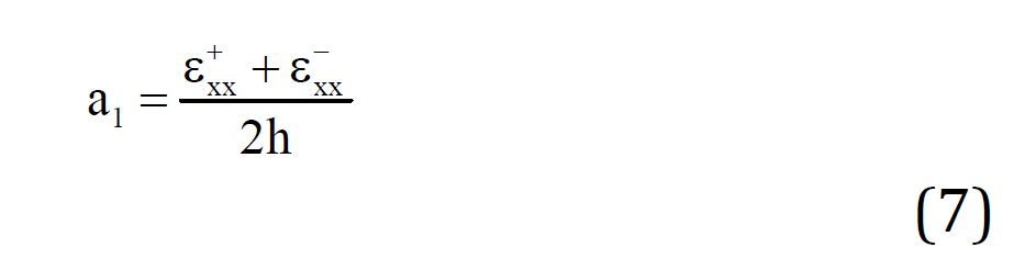
The choice of compressor depends on certain quantities which are: the mass flow rate of the refrigerant to be moved (qm[kg/s]), the volume flow rate that the compressor must aspirate (qva[m3/s]), the theoretical volumetric flow of the compressor or hourly volume swept by the pistons (qvth[m3/s]) [9]. These different sizes are calculated by the following formulas:
Mass Flow Rate to be Displaced of the Refrigerant (qm)
Volume Flow to be Aspirated by the Compressor (qva)
Theoretical compressor flow (or hourly volume swept by the pistons)
With:
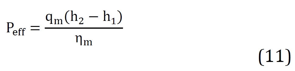
Calculation of the Effective Power on the Compressor Shaft
Power of the compressor drive motor (Pm)
Where:
h7 : Enthalpy at the outlet of the evaporator in [kJ/kg]
h6 : Enthalpy at the outlet of the regulator in [kJ/kg]
h1 : Enthalpy at compressor re-entry in [kJ/kg]
h2 : Enthalpy at the compressor outlet in [kJ/kg]
v1 : Mass volume of the fluid at the compressor inlet in [m3/kg]
0m : Mechanical efficiency of the compressor
0v : Volumetric efficiency
Condenser
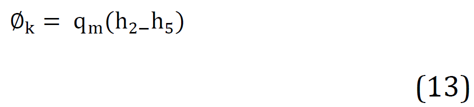
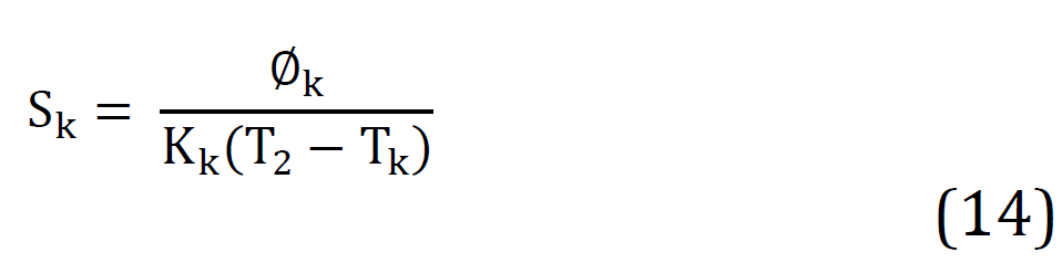
The heat output (Φk) and the exchange surface (Sk) of the condenser are determined respectively by Equations (13) and (14).
Where:
Kk : Global heat exchange coefficient of the condenser in [W/m2K]
h5 : Enthalpy at the outlet of the condenser in [kJ/kg]
Regulator
The selection of the expansion valve is carried out by the manufacturer based on the cooling capacity (Q˙0), the liquid volume flow (vliq), and the pressure drop.
The pressure drop that the regulator must create is )p:
Evaporator
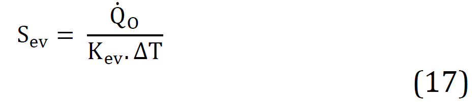
The exchange surface (Sev) of the evaporator is determined by the relation (Equation 17):
Where:
Kev : Overall coefficient of thermal transmission of the evaporator in W/m2K
)T = Tf-To : Temperature difference between the temperature of the medium to be cooled and the evaporation temperature of the refrigerant
Calculation of Pipes
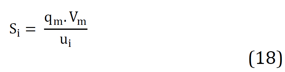
The internal section Si[m2] of the conduits is given by the relation (Equation 18):
Where:
qm : Mass flow rate of the fluid in the pipe [kg/s]
Vm : Mass volume of the fluid in the pipe in [m3/kg]
ui : Fluid velocity in the pipe in [m/s]
Refrigeration System Performance
The performance of the refrigeration system is evaluated by calculating the various coefficients.
Coefficient of Cooling and Calorific Performance of the Real Machine
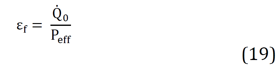
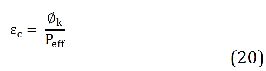
The coefficients of cooling and heating performance of the real machine are determined by relations (Equation 19-20):
The cooling performance coefficient of the real machine is:
The heat coefficient of performance of the real machine is:
Cooling and Heating Performance Coefficients of the Ideal Machine
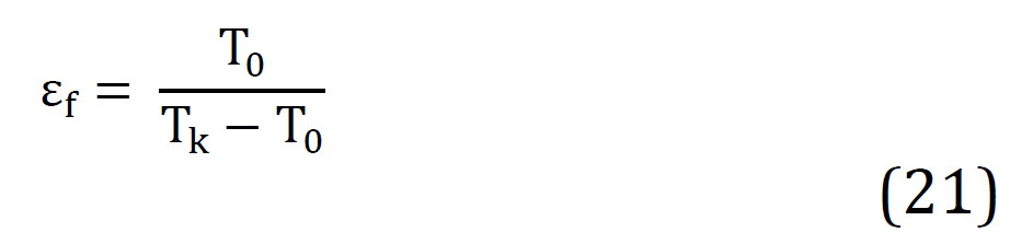
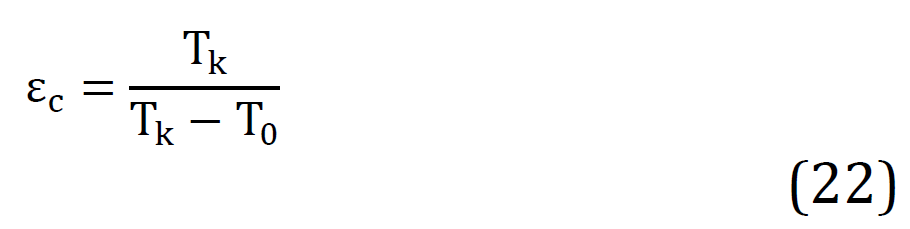
The cooling and heating performance coefficients of the ideal machine are determined by relations (Equation 21-22):
The cooling performance coefficient of the ideal machine is:
Table 1: Characteristics of R22 at the different points of the cycle
Levels
T (°C)
P(bar)
h(kJ/kg)
v1(l/kg)
1
-13
3,3
408
0.752
2
+57
12,00
453
0.960
3
+30
12,00
431
0.852
4
+30
12,00
231
-
5
+25
3,3
250
0.852
6
-23
3,3
250
0.733
7
-23
3,3
401
0.733
1’
-13
3,3
408
0.733
Table 2: Dimensions of the refrigeration system pipes
Pipelines
qm(kg/s)
v1(l/kg)
ui(m/s)
Si (m2)
Matériau
dixde(mm)
Suction
0,045
0,752
8
21,090.10⁻4
Copper
5,080×6,350
Repression
0,045
0,960
12
2,603.10⁻4
Copper
5,080×6,350
liquid
0,045
0,852
1
2,510.10⁻4
Copper
8,000×9,525
The calorific performance coefficient of the ideal machine is:
Sizing of the Refrigeration System
For this step, we used the Manual sizing method.
Choice of Refrigerant
As part of this study, we chose Hydrochlorodifluorocarbon (CHF2Cl) or R22, whose characteristics depend on certain physicochemical parameters.
Condition et hypothèses de fonctionnement du R22
R22 operating conditions and assumptions are as follows:
Q̇o = 7,10 kW, Tex = 25°C, Tcf= -18°C; TSC = 5°C; TSR = 5°C; Pk = 12bar; P0 = 3,3bar ; for τ = 3,63 on a k = 1,230. The relationships from Equation 2 to 6 and the enthalpy diagram of R22, give the characteristics of the different levels of the refrigeration cycle in Table 1.
RESULTS AND DISCUSSION
Sizing of Refrigeration System Components
Compressor: Relations (Equation 7-12) make it possible to calculate the driving power of the compressor motor, with: with : h(1^' )=408 kJ/kg; h6=250kJ/kg; qm=0,045 kg/s; v1=0.752m3/kg; qva=0,0338 m3/s; ηv=0,82; qvth=0,0413 m3/s; ηm= 0,90; P_eff=2,25 kW. Thus, the relation (Equation 12) gives the power of the compressor (Pm = 3kW).
Condenser
We chose an air condenser with an air speed varying between 2 m/s to 4 m/s and with:Kk=35W/m2K;h2=453kJ/kg;h=250kJ/kg;T2=57∘C;Tk=30∘C.
Relations (Equation 8 and 9) respectively give the heat output of the condenser (Φk=9.135kW) and the exchange surface (Sk=9.67 m2).
Regulator
Relations (Equation 15 and 16) respectively give the flow rate of liquid refrigerant received by the expansion valve (Vliq = 0.38×10⁻⁴ m³/h) and the pressure drop that must be generated by the expansion valve (Δp = 8.7 bar).
Evaporator
The chosen evaporator is air and dry expansion with finned tubes, its exchange surface is calculated by relation (Equation 12),With Kev=24 W/m2 K , ΔT=5∘C we have Sev=59 m2.
Calculation of Pipes
The internal section of the pipes is given by relation (Equation 13). The different characteristics of the pipes are given in Table 2.
Refrigeration System Performance
Relations (Equation 19 and 20) respectively give the cooling performance coefficient (εf=3,15) and heating performance of the real machine (εc=4,06).
Relations (Equation 21 and 22), respectively give the coefficient of cooling performance (εf=4,71) and heat of the ideal machine (εc=4,89).
CONCLUSION
This study allowed us to use a sizing model to determine the characteristics of the main components of the cold room which are: compressor, condenser, evaporator, expansion valve, real and ideal coefficient of refrigeration performance. The performance coefficients obtained show that the refrigeration system that we initially proposed for the conservation of fish would function normally. In view of this study, we intend to expand this research on a cold room system operating on the basis of a hybrid system (Photovoltaic-Generator).
REFERENCE
Bjork, Adam and Christoffer Shou Kongstad. Conditions for Design and Control of Refrigeration Systems in Fish Processing Plants. Chalmers University of Technology, 2016.
Enova Næring. Enovas Industriaktiviteter. 2010.
Mendoza-Serrano, D.I. and D.J. Chmielewski. "Optimal Chiller and Thermal Energy Storage Design for Building HVAC Systems." International High Performance Buildings Conference, Paper 117, 2014.
Bah, Mawiatou et al. Etude de l’Alimentation de l’Unité de Conservation du Poisson au Port Artisanal de Teminetaye-Conakry par une Installation Hybride Photovoltaïque-Aérogénérateur. HAL Archives-Ouvertes, 2016.
Rapport Inspection de la Direction Nation de la Pêche et de l’ONUDI sur l’État des Lieux des Ports Artisanales: Section Port Artisanal de Téminétaye. 2009, pp. 24-46.
Affaf, Afif Ouissam et al. Etude et Dimensionnement d’une Installation Frigorifique pour une Usine de Production de Pizzas Fraiches et Surgelées ainsi que de Viennoiseries Surgelées. Projet de fin d’études, Université Saad Dahlab de Blida 1, Algérie, 2019.
Dimensionnement de l’Installation Photovoltaïque du Centre de Santé de Dounet, Mamou, République de Guinée. 2008.
"Sciences et Technologie de l’Industrie et du Développement Durable." Diagramme, jltimin.free, 2015, http://jltimin. free.diagramme.
Silve, Hervé. "Bilan Thermique de Climatisation (Calcul des Charges Thermiques Estivales)." Pagesperso, 2015, http://herve.silve.pagesperso.
Recommended Articles
Research Article
OBSERVATIONS ON THE HOMOGENEOUS TERNARY QUADRATIC DIOPHANTINE EQUATION x2 + 4xy + 9y2 = 21z2
Download PDF
Research Article
Machine Learning-Based Intrusion Detection for Detecting DDoS Attacks in Software-Defined Networks
Zainab Abbas Fadhil
Published: 30/06/2026
Download PDF
Research Article
Computer Driven Library Management and Service Rendering System: Mobile Library Landscape
Yekini N. A,
...
Ojo O
Published: 10/06/2020
Download PDF
Research Article
A Deep Representation Learning Framework Based on PCA-Compressed EfficientNetB0 Embeddings and Neural Spline-Based Classification for Iraqi Banknote Authentication
Saba Hussein Rashid
Published: 30/06/2026
Download PDF
PO Box 101, Nakuru
Kenya.
Email: office@iarconsortium.org
Editorial Office:
J.L Bhavan, Near Radison Blu Hotel,
Jalukbari, Guwahati-India
Lamarana Bah, M., Camara, Y., Camara, S. & Sakouvogui, A. (2021). Sizing Of A Small Capacity Refrigeration Installation (7.10kw) For The Conservation Of Fish At The Thinwgul Market In Mamou In The Republic Of Guinea. IAR Journal of Engineering and Technology, 2(1), 1-5.
MLA
Lamarana Bah, Mamadou, et al. "Sizing Of A Small Capacity Refrigeration Installation (7.10kw) For The Conservation Of Fish At The Thinwgul Market In Mamou In The Republic Of Guinea." IAR Journal of Engineering and Technology 2.1 (2021): 1-5.
Chicago
Lamarana Bah, Mamadou, Yacouba Camara, Sékou Camara and Ansoumane Sakouvogui. "Sizing Of A Small Capacity Refrigeration Installation (7.10kw) For The Conservation Of Fish At The Thinwgul Market In Mamou In The Republic Of Guinea." IAR Journal of Engineering and Technology 2, no. 1 (2021): 1-5.
Harvard
Lamarana Bah, M., Camara, Y., Camara, S. and Sakouvogui, A. (2021) 'Sizing Of A Small Capacity Refrigeration Installation (7.10kw) For The Conservation Of Fish At The Thinwgul Market In Mamou In The Republic Of Guinea' IAR Journal of Engineering and Technology 2(1), pp. 1-5.
Vancouver
Lamarana Bah M, Camara Y, Camara S, Sakouvogui A. Sizing Of A Small Capacity Refrigeration Installation (7.10kw) For The Conservation Of Fish At The Thinwgul Market In Mamou In The Republic Of Guinea. IAR Journal of Engineering and Technology. 2021 Jan;2(1):1-5.



 Download PDF
 Download XML





 is the superheat temperature of the vapor in the evaporator given by the manufacturer.